


In addition to a RIG with AuRiCo, I also own a RIG that can be moved by remote control.
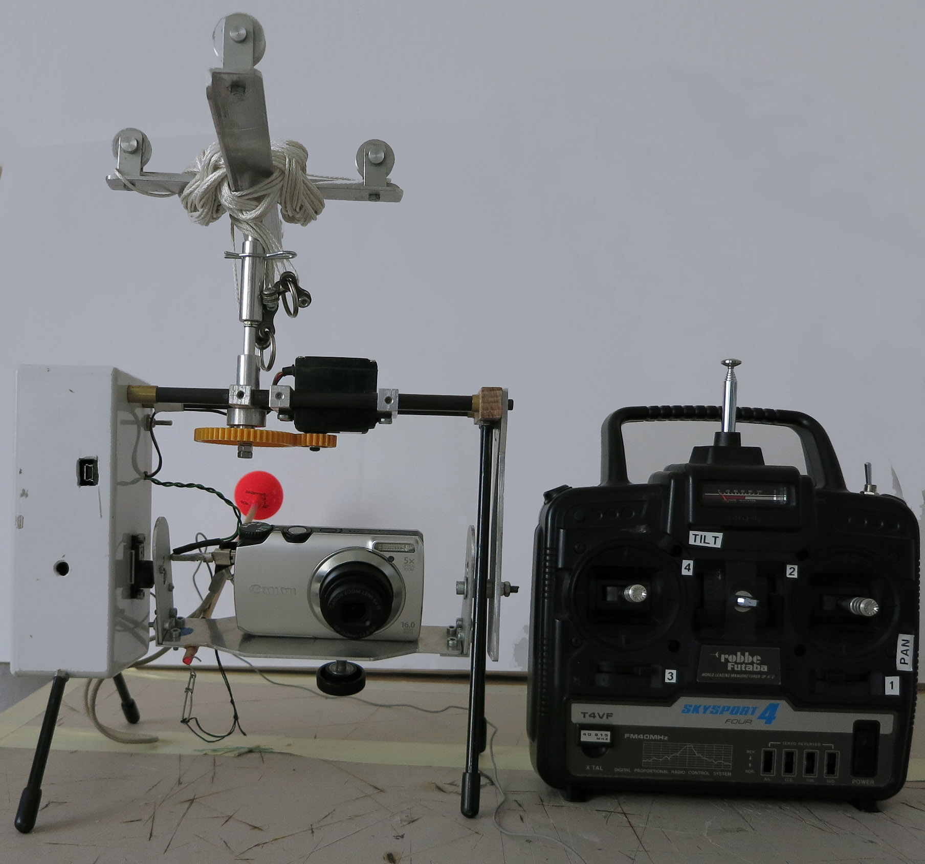 With this transmitter I have 4 channels available with which I can control the individual functions of the RIG: 1. PAN, 2. TILT, 3. Trigger. The triggering is done via an SMD power switch downstream of the receiver and the CHDK programme in the camera.
Since the lever on the remote control panel for the release signal is on the same rocker as the tilt channel, it happened from time to time that I also tilted the camera briefly during the release process due to an awkward movement, which led to blurred or out-of-focus pictures.
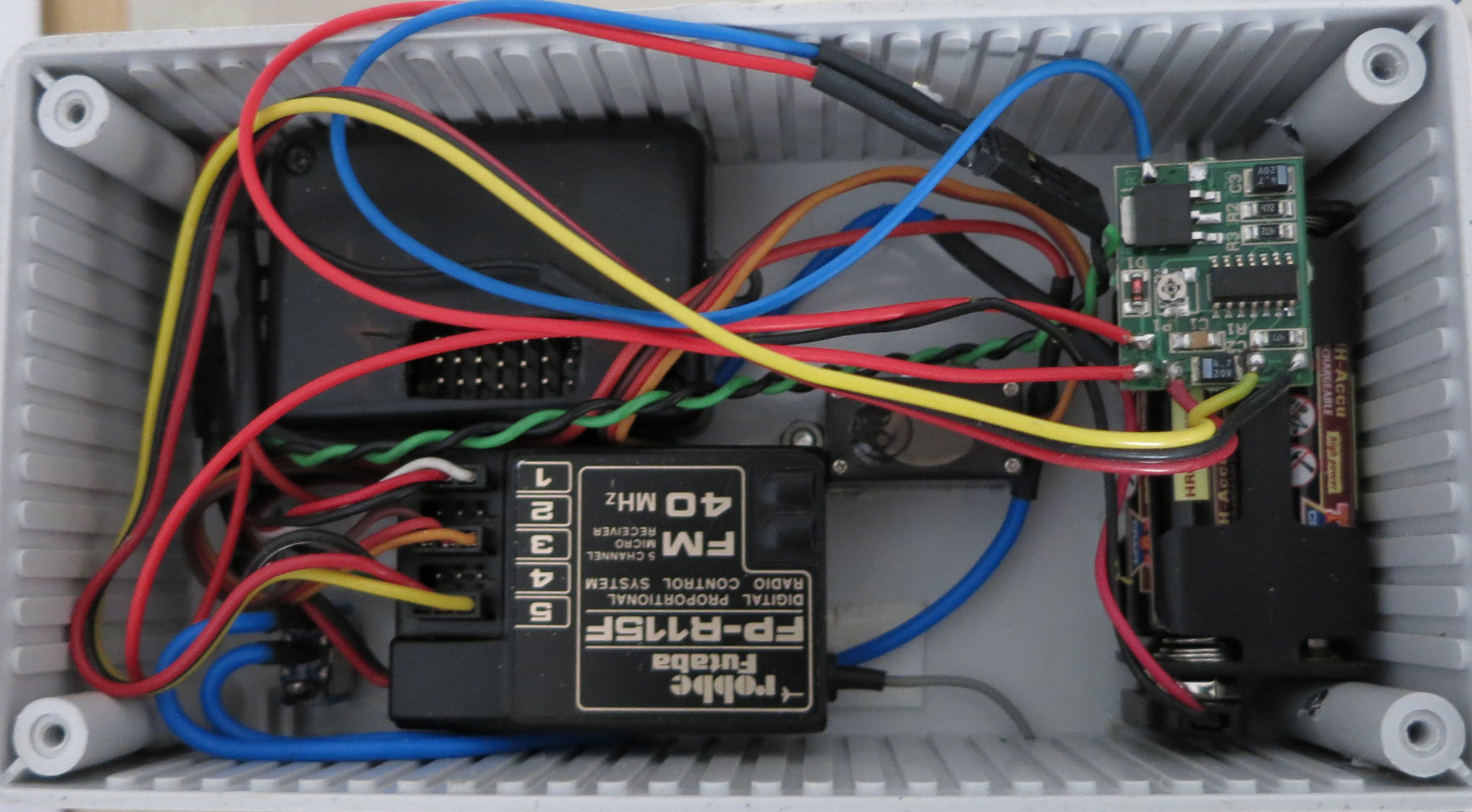
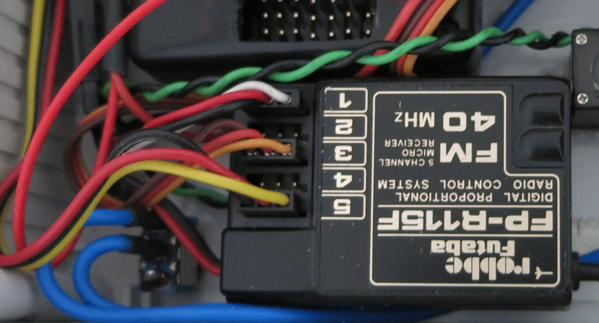
I then looked for a way to trigger the shutter using a separate toggle switch, but I didn’t want to use any of the existing proportional channels for this. Especially as, on closer inspection of the receiver module, I found an unused 5th slot, which naturally lent itself to my project.
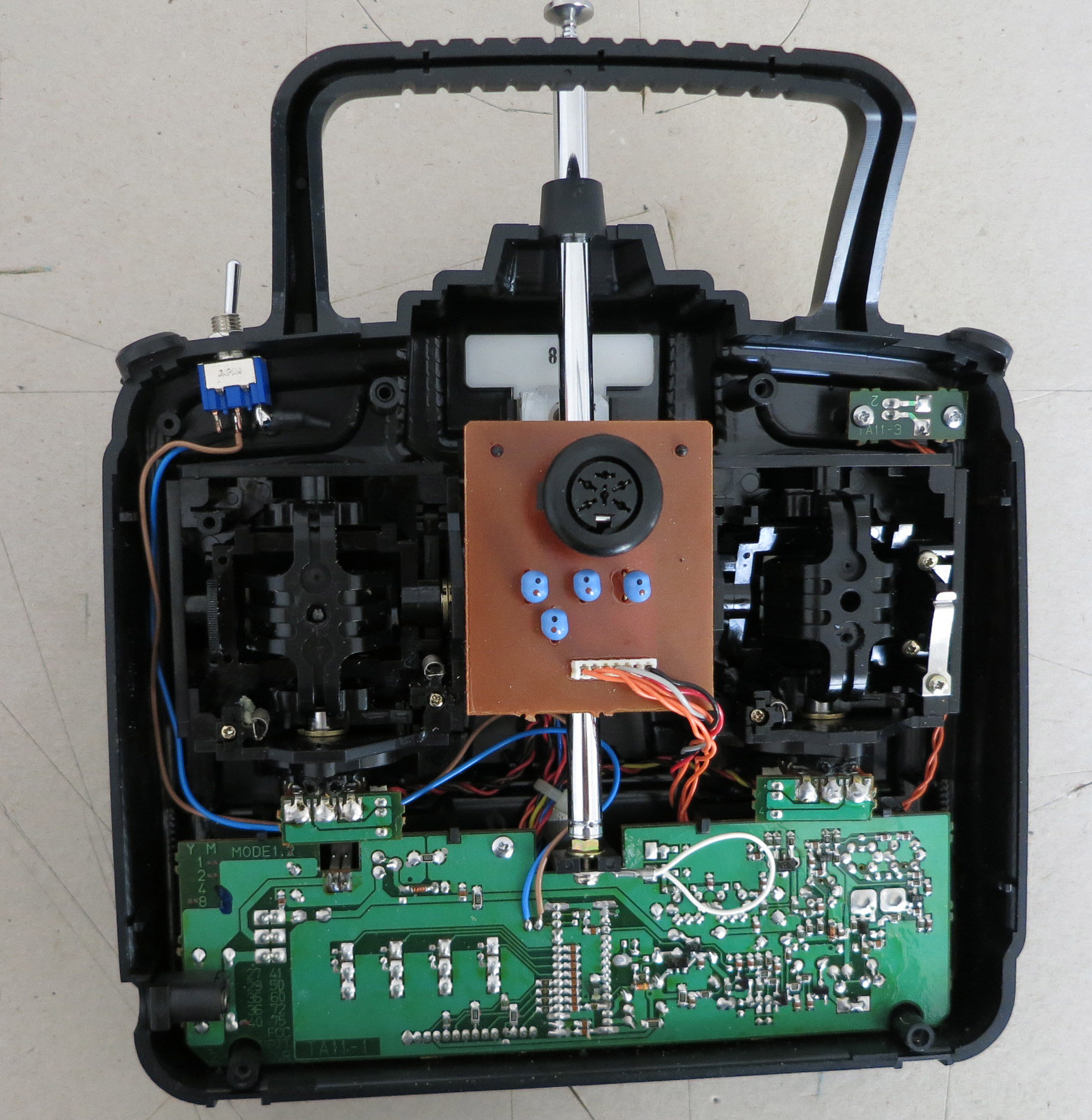
After some research on the net, I came across the information that my remote control actually has 5 channels, but only 4 of them are used as standard. Furthermore, I found instructions on how to use this 5th channel in an Indian RC forum. Many thanks to medicineman1987.
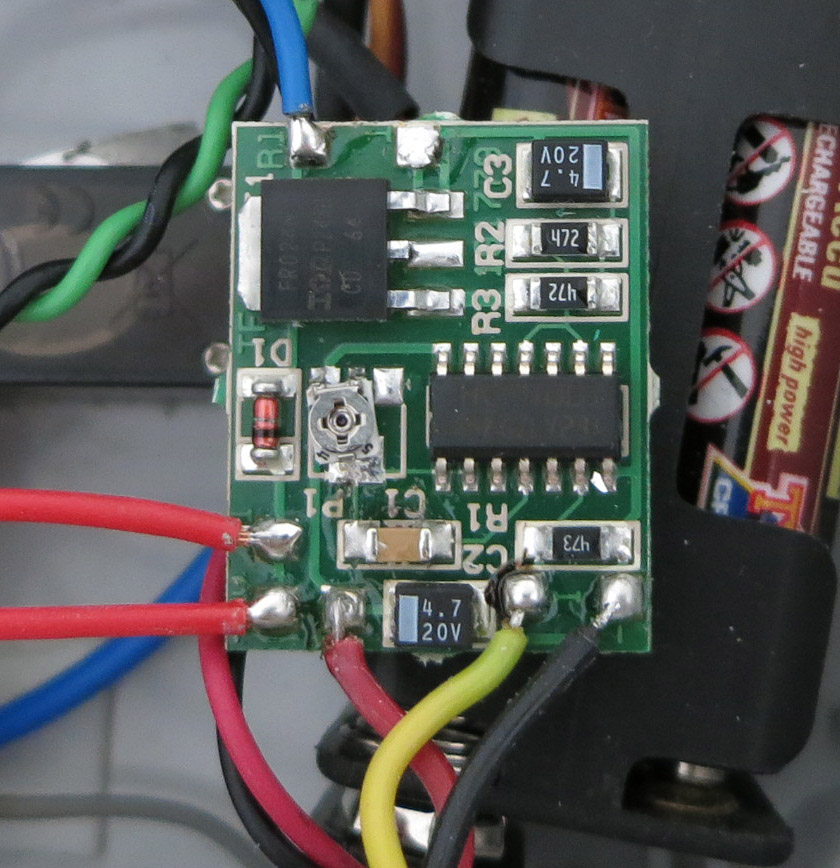
Here is the Futaba extension:
I used the following material and tools for this conversion:
Material:
Cable: single or multi-core, whatever is lying around in your workshop.
Switch: I chose a toggle switch, but any other will do.
Resistor: 540 Ohm (not absolutely necessary, but recommended for safety reasons)
Tools:
7mm drill bit: to drill a hole for the switch in the housing.
Emery, pliers, screwdriver, soldering iron, multimeter (not absolutely necessary, but useful)
Remark:
This conversion only works for a Skysport4 transmitter with the Futaba FP6335 chip. If your transmitter has a NE5044N chip, then you are lucky and can even use 3 additional proportional channels and turn your transmitter into a fully functional 7-channel system. You can find information about this in the relevant RC forums.
The 5th channel is not proportional, i.e. any servo connected to it will move from one extreme position to the other and back when the switch is operated. However, it can also be used, for example, to switch on the lights or, in my case, to trigger them.
Procedure:
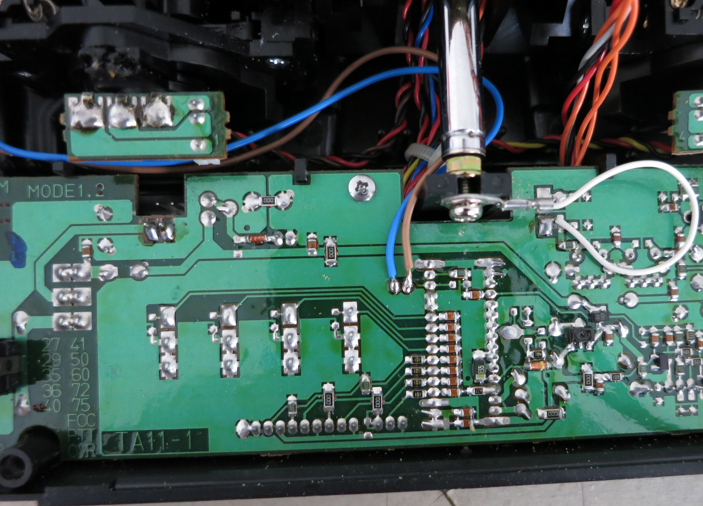
I opened the transmitter housing and drilled a hole where the switch should be. Now I soldered the cables to the switch. I soldered the cables to the switch and added a resistor to one of the cables. The value of the resistor should be in the range of 500 Ohm.
Now I soldered the cables from the switch (and resistor) to the 2 tracks shown in the picture above. In my case, the resistor, protected by a heat shrink tube, is hardly visible directly at the switch. But any other position is possible. I mounted the switch in the case and tucked the cables away inside the case so they wouldn’t get in the way.
Finally I closed the housing again … and the conversion was finished. Simple, quick and clean.
Just for completeness: I don’t give any guarantee for a conversion, everything you do, you do on your own account and risk. 😆
At first tests everything works as desired, now the suitability for everyday use on the airfield has to be shown. Report to follow.