


First of all, an important clarification about the Arduino-RC:
the design of this Arduino-based remote control for a camera rig is not mine, I merely copied it!
Inspired by a post by David Wheeler in the American Aerial Photography Forum, in which he presents his version of a revised rig remote control, I decided to try my hand at this small control unit, which seems to be ideally suited for meadow/beach use. Fortunately David provides an excellent documentation of his work including all used components, sources and programmes. Many thanks for this and of course for his great work on this project.
Photos
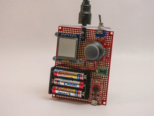
At the heart of the remote control is the Arduino processor, more specifically an Arduino Pro Micro – 5V/16MHz, which provides the remote control module with the PPM signals used to define the servo positions. The operator controls the system by means of a user interface consisting of a thumb joystick and LCD display.
System components of the Arduino RC
The remote control system has an Arduino Pro micro-processor, a thumb joystick as operator interface and an LCD screen for info output. The signals are transmitted from the transmitter module of a Hobbyking 2.4 GHz remote control (HK-T6A). An on/off switch, a voltage regulator and a set of AAA batteries provide the power supply.
The Arduino Pro-Micro from Sparkfun is based on the ATmega32U4, it is quite small, which makes it more attractive for this project than the standard Arduino.
The dedicated timers of this processor generate a PPM signal. And the other connections and functions are also a perfect fit for this project.
It processes the input it receives via a thumb joystick as the operator interface, relays the servo commands via the 2.4 Ghz transmitter module and provides the data for the corresponding display on the LCD module that schematically shows the camera position. It provides visual feedback of the PAN and TILT settings, and it also displays the capture mode, trigger status and horizontal/vertical and auto/manual settings.
Furthermore, the Arduino takes care of the shutter control of the camera: the thumb joystick on the control unit is also used for this. Each time the operator presses the joystick button, a signal is triggered. This signal can be delayed when the rig is in motion. The Arduino waits with the camera trigger signal until the preceding movement has been completed and a short stabilisation phase has been passed.
I removed the transmitter module from a Hobby King remote control.
The power supply is provided by 3 AAA batteries, which supply a nominal 4.5 volts and directly power the remote control transmitter module. (This has its own 3.3 V LDO voltage regulator, so the VCC voltage can have any value greater than 4 volts). However, the 3 AAA batteries also supply a Pololu voltage regulator which generates the 6V voltage for the Arduino. The Arduino’s own regulator reduces the voltage to 5 volts for the ATmega. The LCD display and the joystick are also supplied with these 5 volts.
The interested reader will find more detailed explanations on the pages listed above.
Building description Arduino-RC
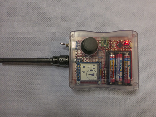
Housing with cover
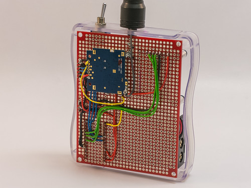
Circuit board
LCD display
Joystick
Arduino
Voltage regulator
Transmitter module with antenna
On/Off switch
Cable and plug